Seismics

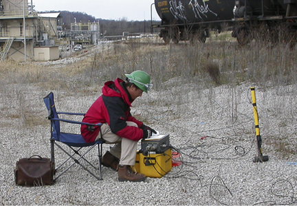
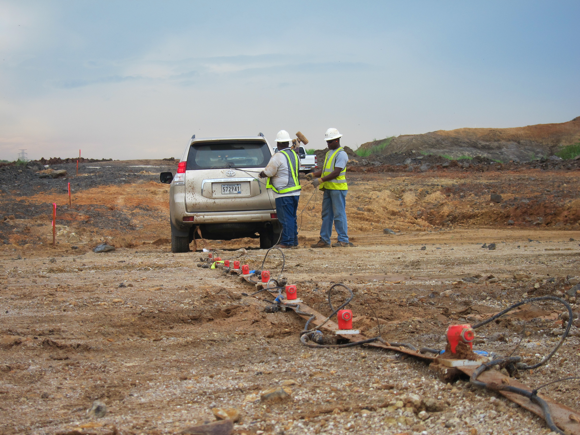
All seismic methods measure the travel-time and frequency of elastic waves as they propagate through the subsurface. The methods commonly used in shallow geophysics involve using an impact source (hammer, weight drop, explosive source) to generate the seismic wave and recording the arrival of the waves with a seismograph and a series of geophones. The types of seismic methods are divided into broad categories on the basis of the geometry of the ray paths (refracted or reflected), the type of energy used (Shear wave, compressional wave or surface wave) and whether the survey is conducted on the surface or in a borehole.
Surface Methods
Seismic Refraction involves measuring the travel time of a body wave as it travels through an upper medium and along an interface of an underlying faster medium and then back to the surface. A hammer or explosive is used to generate the seismic wave. As the wave propagates through the subsurface and reaches an underlying, higher velocity stratum, the wave is critically refracted along that interface. A series of geophones is used to record the travel time of the direct and refracted waves as they reach the ground surface. In accordance with Snell’s Law, seismic refraction will be able to image deeper layers only if they have a higher velocity than the overlying layer. The maximum depth limits are typically 100 to 200 feet seismic refraction is commonly used for:
-
Mapping overburden thickness
-
Determining depth to bedrock
-
Determining rippability of bedrock
-
Geological investigations
Seismic reflection involves measuring the travel time of body waves that are reflected from geologic contacts or manmade structures. As a generated seismic wave reaches an underlying, higher velocity stratum, a portion of the wave is reflected back towards the surface. A series of geophones is used to record the travel time of the reflected waves as they reach the ground surface. The depth of investigation can range from approximately 50 ft to 1000 ft. Seismic reflection is typically used for:
-
Determining thickness and depth of geologic strata
- Evaluating complex geological structures and settings
-
Mapping tunnels, mine shafts and caves
Multichannel Analysis of Surface Waves (MASW)
 MASW is a seismic method that uses surface waves (specifically fundamental mode Rayleigh Waves) to estimate shear wave velocities. Assuming the site has vertical velocity variation (sand to clay to rock), each frequency component of the surface wave will have a different propagation velocity (phase velocity). During the processing of the seismic data, dispersion curves can be calculated from the data of each shot point (record). The dispersion curves show the phase velocity of the surface waves as a function of frequency. 1-D profiles of the shear wave velocity (Vs) versus depth can then be back calculated from the dispersion curve. A series of 1-D shear wave velocity profiles can be combined to produce a 2-D cross-section of the shear wave velocities along the seismic line. MASW is typically used for:
- Locating broad low velocity zones (karst [sinkhole] features, large shallow voids, fracture/fault zones, areas of cut and fill)
-
Mapping stratigraphic layers
-
Determining shear wave velocity for use in calculating dynamic properties of soils
-
V30 measurements
-
Pre-construction site characterization studies (buildings, towers, wind turbines)
Borehole Methods
Seismic Crosshole
The seismic crosshole method is used determine the shear (S) and compressional (P) wave velocities at two or three adjacent borehole locations.
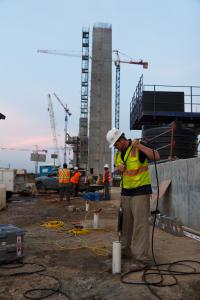
The crosshole method works on the basis of measuring the transit time of P and S-waves generated in one borehole to geophones located at the same depths in one or two nearby boreholes. The principal components of a seismic crosshole system include: an energy source (downhole hammer), one or two vibration detectors (triaxial geophones) capable of being clamped rigidly to the casing at a given depth, and a recording system (seismograph) to record the output from the geophones after inducing S and P-waves in the subsurface. The typical maximum borehole depth is restricted only by the cable length. The boreholes must be a 3 to 6 inches diameter PVC cased borehole and grouted in place. The boreholes are usually spaced 10 feet apart and in-line. Deviation tests for borehole verticality must be recorded and the corrected borehole separation distances must be incorporated in the velocity calculations per ASTM guidelines. The tests are conducted following the ASTM D4428 guidelines.
The seismic downhole method is used determine the shear (S) and compressional (P) wave velocities at one borehole location. The downhole method works on the basis of measuring the transit time of P and S-waves generated at the ground surface to a borehole geophone located at varying depths in a nearby borehole. The principal components of a seismic downhole system include: an energy source (hammer), one to two vibration detectors (triaxial geophones) capable of being clamped rigidly to the casing at a given depth, and a recording system (seismograph) to record the output from the geophones after inducing S and P-waves in the subsurface. The typical maximum borehole depth is approximately 150 ft, but can be deeper in certain circumstances. The borehole must be a 3 to 6 inches diameter PVC cased borehole and grouted in place. This method is typically more cost effective than seismic crosshole testing due to the requirement of only one borehole. The tests are conducted in accordance with ASTM D7400-08.
Click on the Data Samples
Seismic Reflection Data
Seismic Refraction Data
MASW Data
Seismic Crosshole Data

