Underground Utility Locating
Objective
A construction project was planned at a hospital in Miami, Florida. The proposed building expansion was approximately 120 feet by 100 feet in plan dimension. Prior to the start of the construction, all of the underground utilities within the proposed building footprint had to be located and identified. At the time of the investigation, ground cover across the site ranged from grass to asphalt to reinforced concrete.
Method
There were two phases of the investigation. Utility designation was the first phase. Ground penetrating radar and an electronic utility locator were used to locate all utilities within the proposed building footprint. The exact locations of the utilities were marked on the ground surface with marking paint and plotted on a site plan.
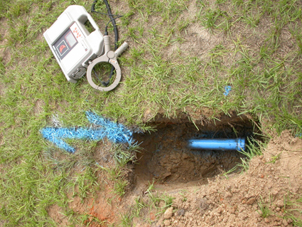
The second phase of the investigation involved using non-destructive vacuum excavation equipment at critical points along the subsurface utility's path to determine the precise horizontal and vertical position, the size, and the composition of the underground utilities.
Results
Twenty-seven utilities were discovered within
the survey area. Twelve vacuum excavation
test holes were performed to identify the
critical utilities. Many of the test holes
were performed at "intersections" of suspected
utilities in order to minimize the number
of test holes and therefore minimize the
cost of the second phase of the survey.
In fact, twenty utilities were identified
within the twelve test holes. The results
of the test holes are presented in Table
1.

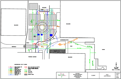
Figure 1 - GPR transect showing five utilities Figure 2 - Test hole identifying the termination of a utility Figure 3 - Site map showing the locations
of underground utilities |